A note up front: I have no real electrical experience or training. If anything in this post is incorrect, please let me know so I can understand it better! ☺️
As I’ve been playing with guitar wiring and learning more, I kept coming across wiring diagrams for different set ups and pickups. You may have found a similar thing, if you’ve looked in places – all the diagrams show you how to physically connect all the cables and switches and where to apply solder, but not why you’re connecting things in the ways you are. As someone who has a life-long passion (see also: bad habit) of asking why, these just aren’t good enough. So I wanted to find out why we wire things the way we do.
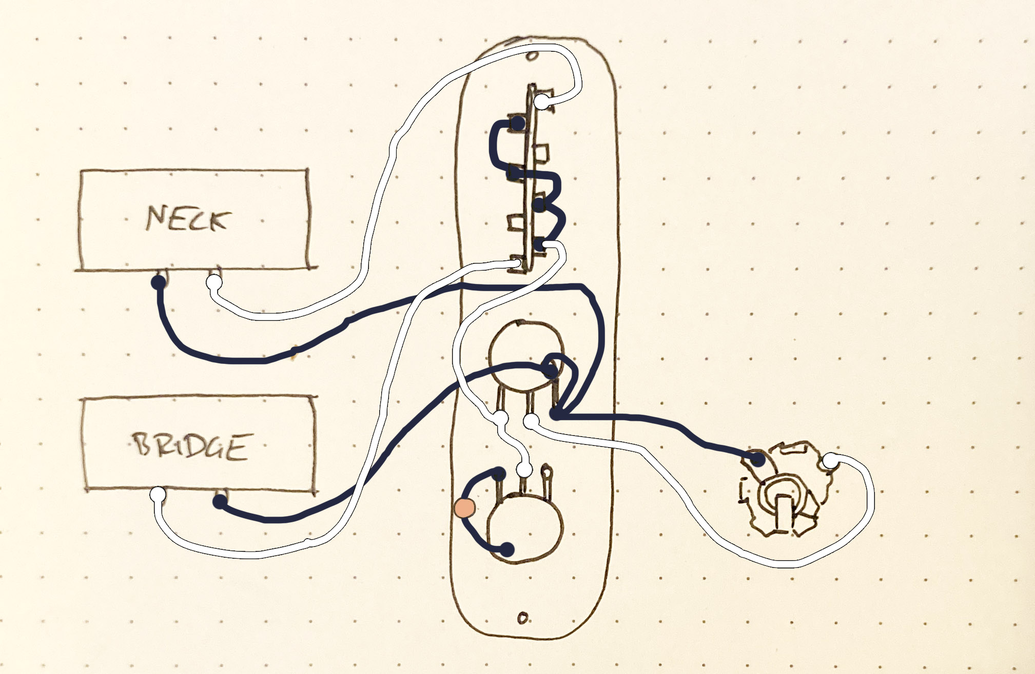
Pictured below is a simple Telecaster circuit, or pictorial circuit diagram, as is usually shown in instructions or as comes with a set of pickups themselves. There is absolutely a benefit to these diagrams, as everything is clearly laid out and understandable. However, it doesn’t give us a clear picture of what’s actually happening to the signal as it passes through the circuit.
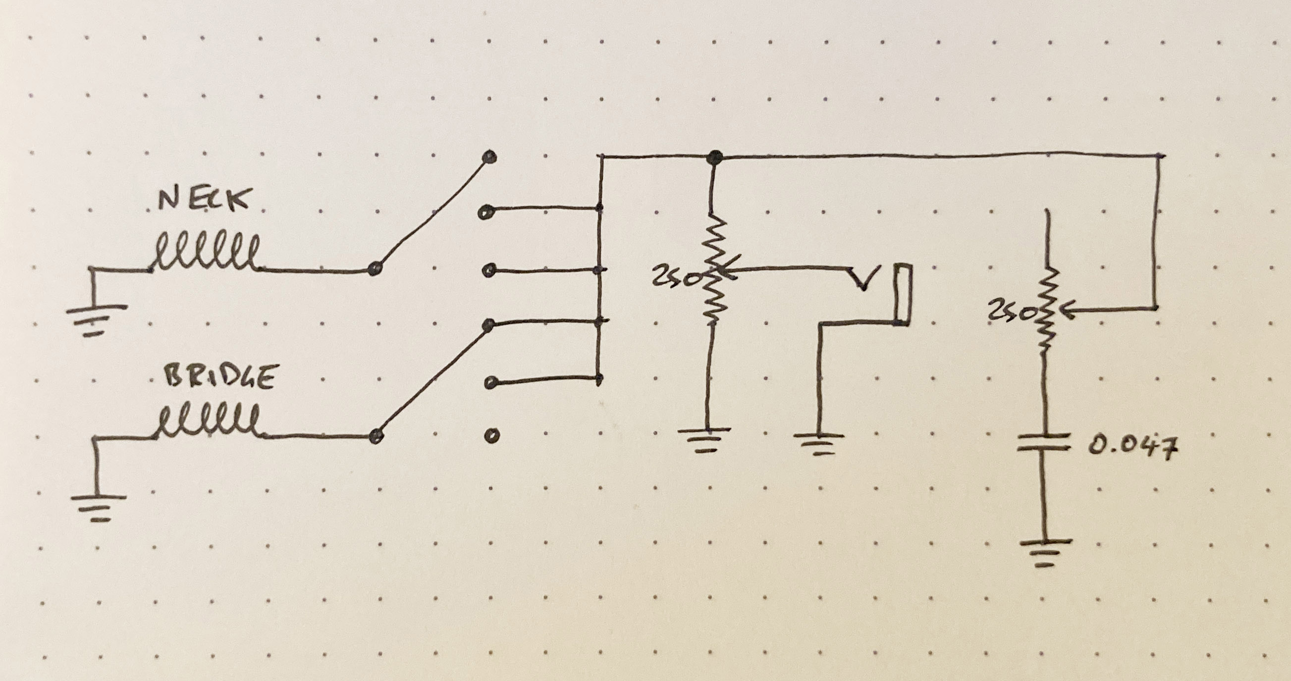
Below is the same circuit but shown as a schematic diagram. It may look more convoluted, but I promise once you understand what it’s saying, it’s not only simple but a great way to understand your guitar circuits much more clearly.
What do schematics show us that pictorial diagrams don’t?

Illustrated above are many of the standard components used in passive guitar wiring illustrated in schematic style.
There are two things I find useful about seeing these circuits as schematics: easily seeing the similarities and differences between different wiring setups, and remembering that all audio signal from guitars is just flow of current.
Maybe this is just a way of laying this out that I’ve found helpful, but in case it helps anyone else I thought I’d write this post.
Note in the diagram above: convention shows resistors and capacitors with their rating beside the symbol.
Resistors, potentiometers, and capacitors
Resistors provide “resistance” to the flowing current. In instruments, this is often used to help match the resistance of other parts of a circuit, ie. a pickup.
Capacitors (sometimes known as tone caps) allow some frequencies to flow through while blocking other frequencies. The higher the value, the more upper frequencies are able to travel through.
Potentiometers are just variable resistors. Pots have a “hot” and “cold” terminal, and a wiper that, when the pot shaft is turned, moves between the other two terminals. A tone pot is just a regular pot with a cap between it and ground.
Note: I’ve not included diagrams for push-pull pots, that will be coming in a future post on the subject.
I’ve included some good further reading links at the end of this blog if you want to learn more about how these components work.
Grounding
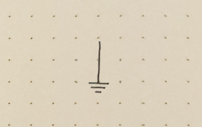
Those three lines that look kind of like an arrow pointing down mean that line is grounded. Where you ground these cables doesn’t actually matter (convention has these cables grounded to the shell of a potentiometer), and so the schematic doesn’t distingush where they are wired. This also helps the schematic remain nice and tidy.
It is also important for our circuits to ground each element only once, and in our schematics we can very easily see if something is grounded more than once.
Switches

Switches are perhaps the least clear part of a circuit, and that’s in part because guitars conventionally use Double Pole (DP) switches, or switches that control two separate circuits at the same time.
In the diagram, on the right, this is shown by the two sets of numbers (0-3) on the left and right of the center line. On the schematic, this is shown as two separate switches that are drawn in alignment to each other.
Guitar switches are also very sneaky - a common standard switch is a 5-way switch, but this is actually just a 3 way switch that has two additional “positions” the switch can be placed in – these positions place the switch’s wiper across two connections, as shown on the table below.
| Pole A | Pole B | |
|---|---|---|
| Position 1 | A0,A1 | B0,B1 |
| Position 2 | A0,A1,A2 | B0,B1,B2 |
| Position 3 | A0,A2 | B0,B2 |
| Position 4 | A0,A2,A3 | B0,B2,B3 |
| Position 5 | A0,A3 | B0,B3 |
You can read more about 5-way switch design on the Seymour Duncan blog here.
A clever design feature of these DP switches is that the 0-position is always the furthest out on each side, which allows you to install them in either direction. If the 0-position was at the same end on both sides, they’d have a correct and incorrect wiring direction, which would be one more thing to consider.
Note: On the schematic, you will note the 0-position wires on the left, and the 1-, 2-, and 3-position wires on the right (bottom to top). The diagonal connected switch between 0 and 3 in the diagram is just convention, it only indicates that it is a switch, not that it needs to be in the 3rd position.
Pickups
Pickups can be illustrated in schematics as a coil of wire with two output leads. I’ve not marked the positive and negative leads on these schematics, but convention will state the negative as going to ground and the positive being wired to the chain of components that lead to the jack.
For humbuckers, there are two coils that are wound in opposite directions and then connected in series (ie. one after the other). I’ve marked these on schematics as having the negative lead of the top connected to the positive lead of the bottom in a clean line, but this will often have to be manually soldered.
Note: For the pickups, there is not a convention per-se, but I’ve included a label to help distinguish pickups: eg. this is where you could write Neck/Middle/Bridge. You can also draw a box around them or not.
What isn’t shown
What a schematic doesn’t show you is exactly where you have to connect all your wires. For those new to circuits, this can be more confusing than a standard diagram as you have to figure out for yourself where all the cables go. However, I think that a diagram and schematic side-by-side gives us the best of both worlds, and helps provide all the information you need to easily wire up your instrument and also understand why the circuit is doing what it’s doing.
Also not shown is wire colours - either standard black/white wire for your circuits, or specific colours for different branded pickups.
A selection of circuits
Modern Telecaster schematic

Above is the schematic for modern Telecaster wiring. Pictured are 7 simple components: two single coil pickups, a 2-pole, 3-way switch, two potentiometers, a capacitor, and an output jack. Unlike the wiring diagram, a few things become instantly obvious about the circuit.
For one, the function of the potentiometers is clear: in the volume pot (in the middle), signal from the pickups enters at the top, and goes to ground at the bottom, with the wiper (the arrow) going to the output jack. As a result, as the pot is turned, the path of least resistance for the current is shifted from ground to the output jack, and respectively from no output to output, and therefore sound.
The tone pot functions in a similar way: hot signal enters via the wiper terminal and the cold terminal is connected to ground through a capacitor. As we looked at earlier, capacitors allow higher frequencies through, so when this pot is wide open, the path of least resistance (for these higher frequencies only) is to ground, and not the output jack.
Finally, the switching is totally clear. There is one position that allows signal from the neck pickup, another position that allows signal from the bridge, and then a position in the middle that allows both. Unlike the wiring diagrams, we can very easily see the switch poles and how they relate here.
I also like representing pickups in these circuits as coils of wire, and therefore as parts that also have resistance. This will come in handy later when we have more coils and other parts working together.
Note: Not pictured is any grounding for the neck pickup cover.
Modern Stratocaster schematic
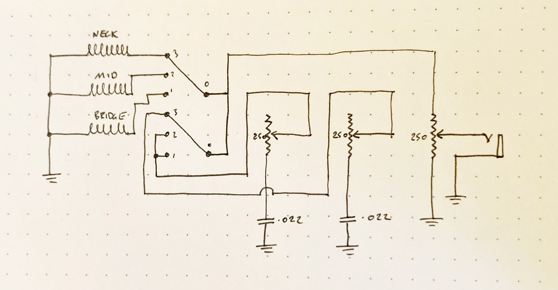
This diagram might look a bit more complex, but is very similar to the tele wiring schematic, just with an additional pickup and pot.
For the sake of the layout, the volume and tone pots have switched places (the volume here is on the far right, and the tone pots are in the middle), but similar to the tele schematic, you can see the volume pot has signal entering from the top, and the tone pots are connected only via the wiper and the bottom terminal. Here you can see clearly why there are two tone pots - one is connected to one terminal of the switch (thus controlling neck tone only), and the other to the other two (thus controlling both mid and bridge tone). You could alter what tone is altered by changing where these are wired, eg. wiring the neck and mid together and having a separate bridge tone, or not using terminals 1-3 on that side of the switch at all and just having a master tone pot.
Stratocaster with blend pot
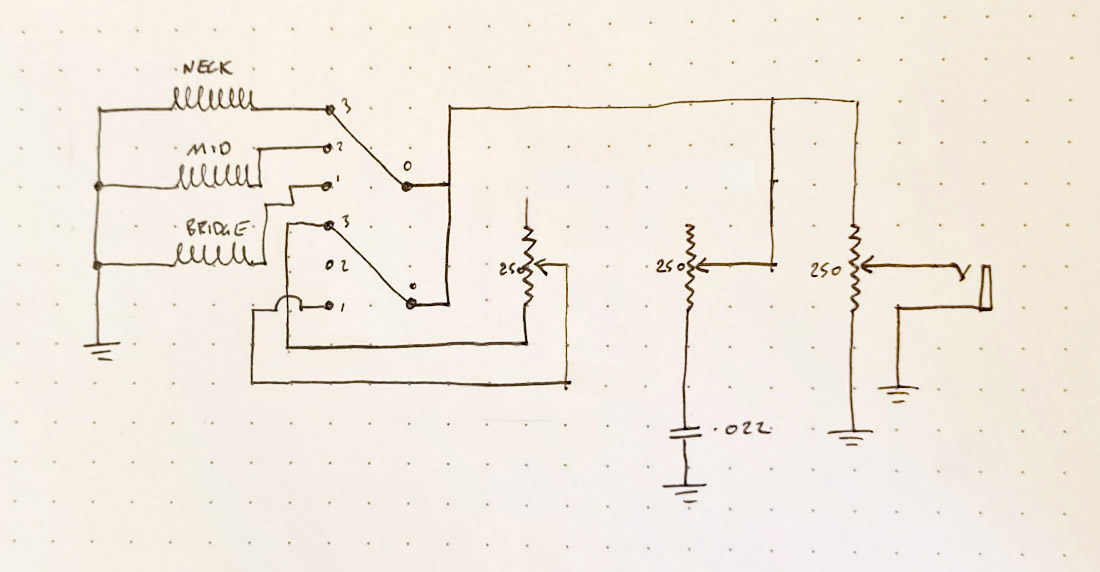
This schematic is very similar to the modern Strat wiring above, but instead has a master tone and a pot that blends the neck and bridge.
Modern LP schematic
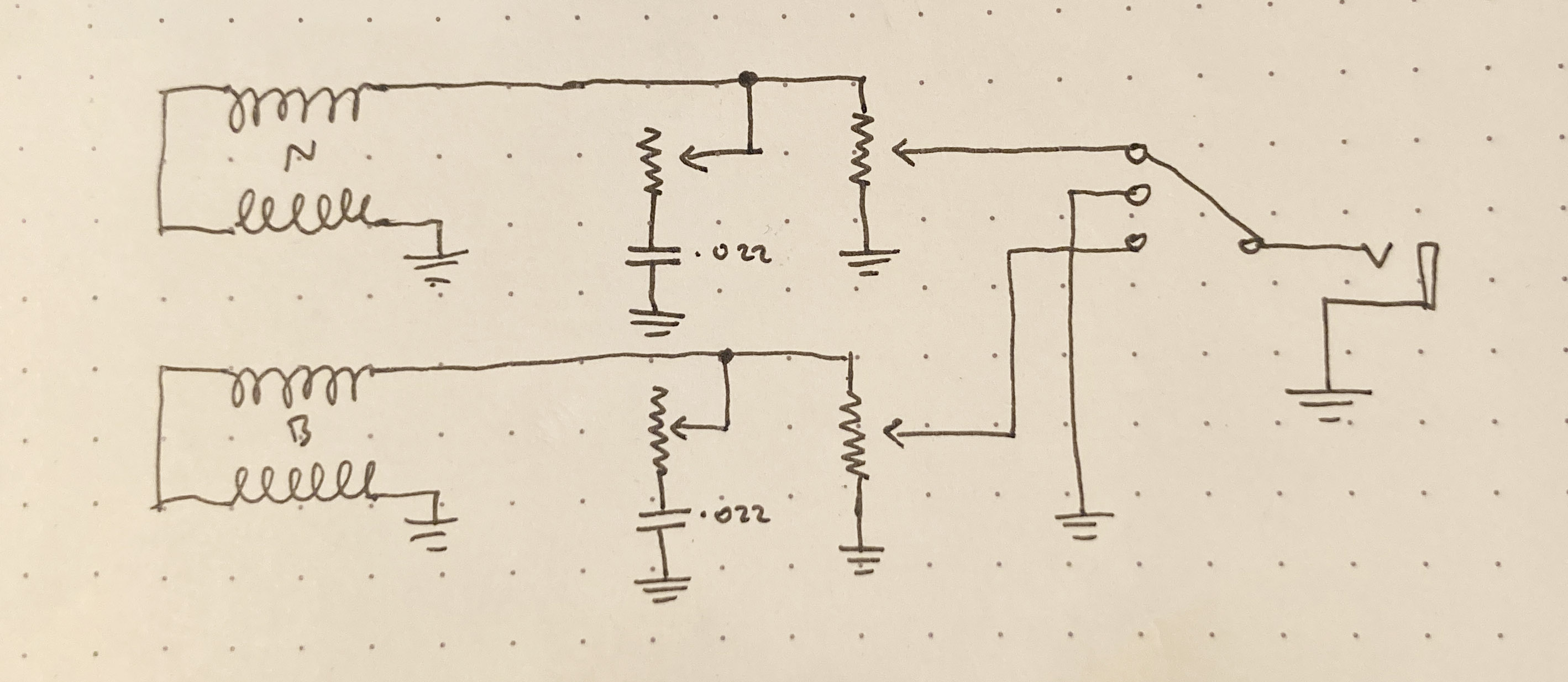
Above is the schematic for a LP-style setup with 2 volume and 2 tone pots and a 3-way toggle switch.
Note that the switch in this wiring setup is a 1-pole switch, and that joining two of the pickup wires together isn’t shown on the schematic.
There are two clear signal paths (from each respective pickup to their tone and volume pots), which are then connected to a switch. We can easily interpret from this schematic that the volume and tone pot for each pickup will only affect that pickup’s volume or tone, and that there is no “master” volume or tone, which is correct.
Why do this?
A good question – it seems to make sense to my brain to see the circuits laid out in this way, and has made clear a number of things that I struggled to understand prior to drawing them out like this, such as grounding, or why things were connected in the ways they were.
As I play more with these, I want to post more about the subject, so stay tuned. I can’t say like and subscribe because I’ve not set this blog up with those features, but you can follow the RSS feed if you’d like.
If you have questions, corrections, or thoughts, please get in touch!
Further reading
Using Resistors In Guitars – 101 - Fralin Pickups
Basic Electric Guitar Circuits 2: Potentiometers & Tone Capacitors - Amplified Parts
Telecaster wiring 101 - Fralin Pickups
Stratocaster Wiring – Tips, Mods & More! - Fralin Pickups
If you enjoyed this post you can get future posts in your inbox at this link.
